


The cross-sectional area is a central quantity in engineering and materials science: it determines how forces are transmitted through a structural element or rock, how stresses arise, and how a material fails under compressive, tensile, or shear loading. In the application fields of concrete demolition and special demolition, building gutting and cutting, rock excavation and tunnel construction, as well as natural stone extraction, the cross-sectional area directly influences the choice of tools and methods—for example, when using concrete pulverizers or rock and concrete splitters from Darda GmbH. Those who correctly assess cross-sectional areas plan more precisely, estimate forces realistically, and work more safely.
Definition: What is meant by cross-sectional area
The cross-sectional area is the area that results when a body is cut by a plane. It is typically specified in mm² or cm². Mathematically, it is the basis for calculating stresses: normal stress σ = F/A and shear stress τ = F/A, where F is the applied force and A is the cross-sectional area. In practice, it describes, for example, the area of a borehole in rock, the wall thickness of a tank multiplied by its circumference at the cut interface, or the effective concrete area between two cracks along which splitting or cutting is performed.
Significance of cross-sectional area in demolition, deconstruction, and extraction
The size and geometry of a cross-sectional area control how high the stresses become during a work step and thereby whether a component breaks in a controlled manner, shears, or plastically deforms. In concrete demolition, the cross-sectional area of walls, slabs, beams, and columns influences which jaw opening and force level a concrete pulverizer requires. With rock and concrete splitters, borehole diameter, borehole depth, and the spacing between boreholes determine the effective splitting area and thus the required splitting force. In rock excavation, cross-sectional areas of layers, joints, and borehole groups are decisive for crack propagation. In natural stone extraction, the cross-sectional area is used to detach blocks in a targeted manner along natural or predefined separation planes. In building gutting, knowledge of the cross-sectional area helps plan the cutting sequence on steel beams, reinforcement, or tank walls, for example when using steel shears or tank cutters.
Geometric fundamentals and typical formulas
A few basic formulas have become established for quick determination of cross-sectional area. In practice, they provide reliable approximations for planning demolition and splitting operations:
- Circle (e.g., borehole): A = π · r² = π · (d/2)²
- Ring (e.g., pipe cross-section): A = π · (R² − r²)
- Rectangle (e.g., masonry cross-section at the cut joint): A = b · h
- Three-sided area (e.g., triangular web): A = (b · h) / 2
- Irregular profiles (e.g., fracture surfaces): segment into simple shapes and sum
For reinforcing steel, the cross-sectional area is determined via the nominal diameter. Example: Aϕ16 = π · (16 mm / 2)² ≈ 201 mm² per bar; for multiple bars, the areas are added.
Influence on stresses, failure patterns, and tool selection
Stresses increase when the cross-sectional area decreases while the force remains constant. This is desirable in cutting operations (concentrated cutting edges), but in splitting it must be applied carefully so that cracks propagate in a controlled manner along a separation plane.
- Concrete pulverizers: The resulting stress in the concrete depends on grip geometry, jaw shape, bearing, and the force imparted by the pulverizer relative to the effective cross-sectional area. Slender wall cross-sections can be gripped differently than massive nodes.
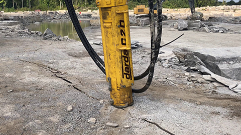
- Rock and concrete splitters: Wedge forces or splitting cylinders generate tensile stresses transverse to the cross-sectional area. Borehole diameter and spacing define the splitting geometry.
- Steel shears and Multi Cutters: The required cutting force is approximately proportional to the cross-sectional area of the profiles to be separated (e.g., rebar bundles, hollow sections, beam flanges).
- Tank cutters: For shell plates, the cross-sectional area is the plate thickness multiplied by the current cutting width; material grade and boundary conditions additionally influence the cutting forces.
Practice in concrete demolition: from estimation to sizing
For rough force estimation, stress levels at which a material begins to crack are often used. In concrete, the splitting tensile strength is on the order of about 2–4 N/mm² (depending on strength class, moisture, age, and crack state). A cautious estimate applies:
Required force F ≈ σ_required · A
Example procedure:
- Determine geometry: wall thickness, height of the planned cut joint, existing reinforcement (scanner/openings).
- Determine effective cross-sectional area A: e.g., A = wall thickness · grip width of the concrete pulverizer or the resulting splitting area between two rows of boreholes.
- Define material assumptions: choose conservative stress assumptions and consider safety margins.
- Select tool and hydraulic power pack so that the available force F_available ≥ F_required, including reserves for reinforcement, eccentricities, and friction.
The actual crack path depends on boundary conditions (support, fixity, degree of reinforcement, crack history). Therefore, assumptions are always validated in practice with trial steps and adjusted if necessary.
Borehole pattern and cross-sectional area in splitting
With rock and concrete splitters, borehole diameter and spacing define the resulting splitting area. Larger boreholes increase the contact area of wedges or splitting cylinders, while the spacing of the holes defines the continuous cross-sectional area between the bores. The more homogeneous the material and supports, the more evenly the tensile stress is distributed over the area. In layered natural stone or heavily reinforced concrete, targeted adjustments of the pattern may be necessary to promote a desired crack line.
Reinforcement and steel cross-sections: cutting, clamping, separating
For reinforcement, beams, and profiles, the metallic cross-sectional area determines the necessary cutting force. For a first estimate: Cutting force ∼ shear strength of the material × cross-sectional area. Multiple bars add up in area; bundles or mats create local peak loads at the cutting edges. For planned separation cuts, the profile geometry (e.g., I, U, rectangular tubes) is broken down into partial areas so that the cutting sequence and gripping positions can be defined safely.
Fields of application and product-related examples
Concrete demolition and special demolition
For ceiling openings or the deconstruction of wall panels, cross-sectional area analysis supports the choice of the concrete pulverizer: jaw opening, jaw geometry, and positioning along load-bearing or already weakened regions determine how loads are transferred into the remaining cross-sections. The goal is controlled crack propagation without unintended deviations.
Rock excavation and tunnel construction
In rock, borehole cross-sections and joint planes define the splitting areas. Rock splitting cylinders transfer forces into the borehole wall, generating tensile stresses across the cross-sectional area of the in-situ rock. An area assessment adapted to the geology minimizes uncontrolled spalling.
Natural stone extraction
When detaching raw blocks, natural separation planes with defined cross-sectional areas are incised. Rock and concrete splitters generate the required tensile stress along these areas. Block quality benefits when the effective area is sized to match the anisotropy of the rock.
Building gutting and cutting
In building gutting, concrete pulverizers, steel shears, Multi Cutters, and tank cutters encounter varying cross-sections: from thin-walled sheet cladding and pipelines to massive steel beams. The selection and setting of the tools are guided by the area to be severed and the material grade so that cutting forces, feed rate, and heat input remain manageable.
Measurement, documentation, and quality assurance
Cross-sectional areas are taken from drawings or determined on site. Suitable methods include dimensioning with tape measure, caliper, or core drilling to determine diameters. For reinforcing steel, diameters are marked and the number of bars per section documented. When locations are unknown, minimally destructive locating methods help to realistically define the effective concrete area. Clear documentation of assumptions supports subsequent evaluation of force and time requirements.
Typical sources of error and their avoidance
- Neglecting the actual gripping or splitting width: the real effective cross-sectional area often deviates from the nominal component area.
- Underestimating reinforcement areas: multiple layers or bundled bars significantly increase the area to be cut.
- Edge and support effects: fixed or partially unloaded cross-sections change the stress distribution.
- Inhomogeneities in the material: structural defects, honeycombing, or joints can greatly reduce the effective area.
- Lack of safety margins: conservative stress assumptions and appropriate reserves in the hydraulic power pack increase process stability.
Safety and planning aspects
Work that introduces forces into structural elements or rock via cross-sectional areas requires careful planning and appropriate safety measures. Information on strengths and force estimates is to be understood as general, non-binding guidance. For specific projects, local conditions, standards, and permissible loads are decisive. A step-by-step approach with trial loadings, observation of crack formation, and adjusted parameters contributes to a controlled and safe process.
Guide for tool selection by cross-sectional area
- Small to medium concrete cross-sections with local weakening: concrete pulverizers with suitable jaw opening and appropriate jaw geometry.
- Massive concrete or natural stone cross-sections: rock and concrete splitters; match borehole diameters and spacings to the desired splitting area.
- High steel content or pure steel cross-sections: steel shears or Multi Cutters; use the cross-sectional area of the profiles as the primary design parameter.
- Thin-walled, large-area metal cross-sections (vessels, tanks): tank cutters; plan cutting sequence and support according to area stiffness.
- Hydraulic power pack: select appropriate hydraulic power units so that the required forces including reserves are available over the entire working stroke.