


Lattice girder beams — also known as truss girders in steel construction and often used as reinforcement lattice girder beams in filigree precast floor slabs — combine high load-bearing capacity with low self-weight. They are found in hall roofs, bridges, falsework, formwork, and precast construction. During deconstruction, they place special demands on planning, stability, and separation methods. Especially in selective demolition of steel trusses or in removing reinforced concrete slabs with embedded lattice girder beams, hydraulic tools such as concrete pulverizers as well as rock and concrete splitters prove effective, operating with low vibration, control, and precision.
Definition: What is meant by a lattice girder beam
A lattice girder beam is a bar-type structural system with a top and bottom chord connected by diagonals and, if necessary, verticals. Loads are transferred as normal forces through the members and nodes; this enables long spans with slender cross-sections. Essentially, two variants are distinguished:
- Steel truss girder: bolted or welded, with gusset plates, frequently used in roof and bridge structures. They can also be partially embedded in concrete as composite members.
- Reinforcement lattice girder beam in precast construction: factory-welded lattices (top chord, bottom chord, diagonals) made of reinforcing steel that stiffen thin precast slabs (filigree slabs) and, after the cast-in-place concrete pour, carry loads together with the slab.
Construction and functional principle of lattice girder beams
The load-carrying behavior of the lattice girder beam is based on the force-flow-compatible interaction of chords and diagonals. The top chord generally takes compression, the bottom chord tension; the diagonals redirect shear forces. Nodes are formed via gusset plates, splice plates, or full-strength connections. In composite solutions, the lattice girder beam is partially encased in concrete; shear connectors ensure composite action.
Steel trusses and composite solutions
In steel trusses, cross-sections, member inclinations, and panel lengths are designed for bending moments, shear, and buckling verification. Node regions are highly stressed, which is why notch effects, weld quality, and corrosion protection are decisive. Composite constructions use concrete for compression and steel for tension, enabling efficient material utilization.
Lattice girder beams in filigree slabs
Reinforcement lattice girder beams provide precast slabs with transport and erection strength, fix the position of the top reinforcement, and act as a spatial load-bearing system after concreting. Typical features are regular spacing, defined embedment depths, and sufficient rebar lap splices. During the deconstruction of floor slabs, these lattices influence crack paths and the sensible sequence of fragmentation.
Fields of application and typical uses
Lattice girder beams are encountered by construction and deconstruction teams in many situations — as load-bearing elements in new construction, as structures to be dismantled in demolition, or as auxiliary structures:
- Hall and bridge construction: long spans, slender structures, often with composite portions.
- Falsework, formwork, site equipment: temporary beams and frames.
- Precast and cast-in-place concrete slabs: lattice girder beams as reinforcement and stiffening elements in filigree slabs.
- Tunnel and specialist foundation engineering: lattice elements in form travelers and falsework; deconstruction during modifications or refurbishments.
- Deconstruction contexts: concrete demolition and deconstruction, strip-out and cutting, and special operations with requirements for spark-free work, reduced vibration, and noise mitigation.
Deconstruction of lattice girder beams made of steel
When removing steel truss lattice girder beams, the structural stability of the remaining structure is paramount. Load paths change with every separation cut; temporary shoring and a defined cutting sequence are therefore indispensable. Hydraulic cutting technology enables cold separation — with reduced sparks and controlled action — an advantage in sensitive areas.
Cutting sequence and stability
- Survey of existing conditions: record geometry, nodes, connections, corrosion, and any composite portions with concrete.
- Plan load redistributions: shore, suspend, or relieve before opening nodes.
- Create partial sections: release panels and nodes in sequence to prevent uncontrolled twisting.
- Consider residual stresses: avoid oblique start cuts; choose access to minimize pinch hazards.
- Final works: secure chord ends, exclude falling parts, mark cut edges.
Tools for separation
Hydraulic steel shears, combination shears, and multi cutters are suitable for members, chords, and nodes. They cut sections, round bars, and plate without thermal influence. Hydraulic power units provide the required pressure with compact dimensions — advantageous in confined steel trusses. If nodes are cast in concrete, the concrete is exposed with concrete pulverizers; the steel parts can then be separated mechanically.
Concrete pulverizers and lattice girder beams in reinforced concrete
For slabs or downstand beams with integrated lattice girder beams, the concrete pulverizer allows controlled exposure of the reinforcement. The tool nibbles the concrete along the lattice diagonals until bars are exposed and can be cut or pulled out in a targeted manner. The method is low-vibration and thus suitable for strip-out and cutting in areas close to ongoing use.
Work sequence for filigree slabs
- Define a field-by-field approach: relieve support zones first, dissolve the diaphragm action of the slab.
- Determine separation depths: set cuts along slab joints and edge downstand beams.
- Remove concrete with the concrete pulverizer: expose lattice diagonals, identify reinforcement.
- Cut steel reinforcement: cut round bars with combination shears or multi cutters, taking offsets and prestressing into account.
- Secure and lower sections: small-piece fragmentation reduces fall energies and noise.
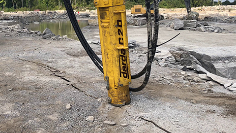
Stone and concrete splitters at supports of lattice girder beams
Massive support zones, corbels, or concreted nodes can be opened in a targeted manner using stone and concrete splitters. Inserted stone splitting cylinders create crack lines that deliberately weaken the concrete. This facilitates exposing the support reinforcement and reduces the risk of uncontrolled break-offs — a plus in concrete demolition and special demolition as well as in special operations, where vibration, dust, and sparks must be minimized.
Cut guidance and separation techniques in sensitive environments
In areas with fire or explosion hazards, cold methods are preferable. Hydraulically operated steel shears, multi cutters, and concrete pulverizers reduce sparks and avoid heat input. For combined construction methods (steel truss encased in concrete), a sequence of exposing, splitting, and then cutting is recommended to gradually eliminate composite action.
Protective measures, emissions, and environmental protection
Dust, noise, and vibration can be minimized by small-piece fragmentation, water misting, low-vibration splitting techniques, and adapted cutting sequences. Load-bearing laydown areas, orderly material separation, and short transport routes support clean site logistics and facilitate material recycling of concrete and steel.
Planning and documentation
Before starting, structural documents, construction stages, and any changes from the existing structure must be reviewed. Temporary works (shoring, suspensions) are calculated and adapted to the actual geometry. In case of uncertainties, exposures using concrete pulverizers or exploratory openings help. A separation and disposal concept, evidence of the structural stability of temporary states, and a photo log of cut and split points are kept up to date. Legal requirements and safety rules must be observed according to location and project; specific evaluations are always carried out on a case-by-case basis by the responsible specialists.
Practice: site guidance
- Clarify load paths: open chords and nodes only after unloading.
- Ensure accessibility: work field by field, plan work platforms and set-down areas.
- Match tools: concrete pulverizers for exposing, stone and concrete splitters for massive zones, steel shears and multi cutters for sections and round bars; size hydraulic power packs appropriately.
- Reduce emissions: use water misting, low-dust sequences, and cold separation methods.
- Material separation: collect steel from nodes and chords separately; remove concrete debris sorted by type.