


Sloped screed ensures that water drains in a targeted way instead of remaining on surfaces. It is indispensable in structures with high moisture exposure: on flat roofs, terraces, balconies, in wet rooms, in parking decks, and in technical areas with drains or drainage channels. In new construction and refurbishment, the correct slope geometry influences moisture protection, surface durability, and operational safety. In deconstruction or when repairing faulty sloped surfaces, gentle, low-vibration removal of screed and concrete layers plays a role — here, in the context of concrete demolition and special deconstruction, hydraulic tools such as concrete demolition shear or hydraulic rock and concrete splitters are frequently used, as offered by Darda GmbH.
Definition: What is meant by sloped screed
Sloped screed is a screed system produced with a defined angle of inclination to direct surface water in a controlled manner to drains, drainage channels, or drip edges. Typical slopes are about 1–2%, depending on the application and the respective technical rules. The sloped screed can be executed as a bonded screed, on a separation layer, or as a floating screed and is usually made of cement screed, less often of calcium sulfate or lightweight screeds. It differs from leveling screed in that the focus is not on flatness, but on deliberate inclination for reliable water drainage.
Areas of application and mode of action of sloped screed
Sloped screed is used where moisture occurs permanently or periodically and must be removed quickly. This includes flat roofs with waterproofing, weather-exposed exterior areas such as balconies and terraces, wet rooms with point or linear drainage, commercial kitchens, wash bays, parking structures, and technical operating areas. Thanks to the slope, water drains without ponding, protecting the substructure from wetting and frost–deicing-salt damage.
The functionality results from the interplay of slope geometry, material selection, substrate adhesion, and the waterproofing and surfacing system. Decisive is a continuous drainage chain: from the surface via joints and edges into drains, emergency overflows, or drainage channels. A homogeneous, predictable slope prevents standing water and reduces the risk of crack formation due to frost, thermal length changes, and chemical exposure.
Planning, slope geometry, and normative notes
Planning begins with determining the drainage points. From there the slope is developed in the flow direction. Typical inclinations range between 1% (interior areas with controlled drainage) and 2% (exterior areas, higher driving rain exposure). For large-format finishes, high flatness requirements, or multiple drainage points, slope wedges and slope transitions must be taken into account. Connection details at door thresholds, parapets, penetrations, and inlets must be designed so that neither capillary water nor ponding occurs.
Depending on the code and material system, specifications for minimum layer thickness, surface pull-off strength, residual moisture, and waterproofing must be observed. Such information is general and must be adapted to the specific case; it does not replace project-specific planning.
Typical construction types
- Bonded screed with slope: directly on load-bearing concrete; requires a bonding bridge and sufficient surface pull-off strength of the substrate.
- Screed on separation layer: for moisture-sensitive substrates or when movements should be decoupled.
- Floating screed: on insulation layers, e.g., in roof build-ups; load-bearing capacity and compressive strength of the insulation layers are crucial.
Material selection and execution steps
Cement-bound, earth-moist screed mortars with suitable particle-size distribution are frequently used for sloped screeds. Depending on the construction sequence, fast-setting mortars or polymer-modified systems are suitable to achieve early readiness for covering and reduced shrinkage. In roof build-ups, lightweight screeds are also used to minimize loads.
- Prepare the substrate: clean, expose load-bearing zones, strengthen voids and cracks.
- Apply a bonding bridge or separation layer; install edge insulation strips at all upstands.
- Set out the slope: datum marks, laser, gauges; set drains to the correct elevation.
- Place, strike off, compact the screed, and finish the surface as required by the system or shot-blast it.
- Curing: ensure moisture protection, control temperature, avoid shrinkage cracking.
- Verify: slope, flatness, surface pull-off strength, residual moisture.
Quality assurance: test criteria for sloped screeds
Key parameters are uniform inclination, sufficient compressive and flexural tensile strength, surface pull-off strength for subsequent waterproofing or coatings, standard-compliant flatness within the function (e.g., edge pattern of large-format finishes), and the residual moisture at the time of covering. Spot-check slope measurements, pull-off tests, and documented curing reduce the risk of defects.
Common failure patterns and causes
- Ponding: insufficient or interrupted slope, settlement or deformation within the build-up.
- Cracking: missing expansion joints, shrinkage stresses, uneven drying.
- Debonding: inadequate substrate preparation or deficient bonding bridge.
- Spalling/frost damage: standing water, insufficient freeze–deicing-salt resistance.
Depending on the damage pattern, partial deconstruction and local slope corrections are required. In repair, precise, low vibration levels methods are often preferred to avoid impairing adjacent components and waterproofing.
Repair, deconstruction, and removal of sloped screed
In the case of faulty slopes, damaged waterproofing, or changes of use, sloped screeds must be removed completely or partially. In practice, low vibration levels, controllable methods are used to protect utility lines, insulation, and adjacent structural elements and to limit emissions.
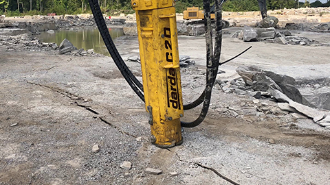
In these tasks, hydraulic tools have proven themselves. Concrete demolition shears enable targeted biting off and crushing of screed- or concrete-like layers, including at edges, without high impact energy. Hydraulic wedge splitters act from the inside out: drill a borehole, place the splitting cylinder, and open the composite in a controlled manner — advantageous with thicker, high-strength, or aggregate-rich sloped layers. Power units from Darda GmbH supply these devices energy-efficiently, even in confined existing structures.
Work sequence in deconstruction
- Survey the existing structure: layer build-up, utility lines, waterproofing layers, structural boundary conditions.
- Emission protection: dust suppression and noise reduction measures, dust extraction plant and containment.
- Pre-scoring or drilling of starting points, marking the deconstruction areas.
- Local splitting with hydraulic wedge splitters, biting with concrete demolition shears; material control and demolition sorting.
- Expose drains and drainage channels, protect substructures and connections.
- Areal residual removal and substrate preparation for the new build-up.
For inserts of reinforcement or embedded components, combined shears, steel shear, or multi cutters can be used depending on the situation to separate metallic components without unnecessarily damaging the mineral layers. This supports clean separation of the material flow for recovery.
Interfaces with concrete demolition, building gutting, and tunnel construction
Designers and contractors encounter sloped screeds not only on roofs and balconies. In drainage areas of tunnels, galleries, and technical shafts, sloped layers carry away seepage or cleaning water. During upgrades in rock breakout and tunnel construction, the deconstruction of fillets and floor slopes is often part of the construction sequence. Here, low vibrations and compact tool geometry are decisive — characteristics that favor the use of wedge splitting cylinders and concrete demolition shears for controlled special demolition. In building gutting and cutting, hydraulic shears facilitate exposing drainage points before new slopes are formed.
Detail points: connections, drains, and joints
Connections at door thresholds, parapets, and upstands must be designed with safe heights and watertightness. Drains should be installed flush and without hollows. Expansion joints accommodate length changes of the build-up; they should be laid out straight and coordinated with the slope geometry. Precise execution of these detail points minimizes later interventions and extends service life.
Safety, environment, and disposal
During installation as well as deconstruction, protective measures against dust, noise, and vibrations must be considered. Mineral demolition debris should be kept separated by type wherever possible to open up recycling routes. In sensitive environments, such as hospitals, laboratories, or listed buildings, a low-vibration approach with hydraulic splitting and shear technology is often advantageous. Legally binding requirements must be checked project-specifically; the notes given are general.
Practical recommendations for durable slopes
- Define drainage points early and control them during construction.
- Coordinate substrate and bonding bridge; verify surface pull-off strength.
- Ensure sufficient minimum layer thicknesses and slope continuity; avoid reverse slopes.
- Select suitable material systems (fast-setting mortar, lightweight screed, polymer modification if necessary) to match the construction schedule.
- Align joint planning with the slope geometry; consistently form edge and expansion joints.
- For corrections and deconstruction, rely on controllable, low vibration levels methods, e.g., concrete demolition shears or hydraulic wedge splitters with suitable hydraulic power packs from Darda GmbH.