


The relief cut is a proven procedure in controlled deconstruction that reduces material stresses and deliberately guides crack paths. In concrete, masonry, and natural stone, it serves to separate components safely, protect edges, and avoid uncontrolled spalling. In combination with tools such as concrete demolition shears, rock and concrete splitting devices, or steel shears and tank cutters by Darda GmbH, the relief cut helps to perform work with low vibration, predictability, and material-appropriate methods—particularly in sensitive environments and confined spaces.
Definition: What is meant by a relief cut
A relief cut is a deliberately created cut, slot, or kerf that locally reduces a component’s stiffness and internal restraint to release stresses and guide the crack or separation joint. Depending on the material and task, the relief cut is made by sawing, milling, core drilling with slotting, or—in metals—by shearing or thermal methods. The aim is to make the subsequent intervention, such as breaking with concrete demolition shears or the hydraulic splitting of rock and concrete, predictable, to protect adjacent structures, and to improve the quality of the separation edge.
How it works and objectives of the relief cut
Mechanically, the relief cut creates a defined weakening where stresses can be relieved and cracks preferentially propagate. This allows specifying separation directions, reducing local tensile stresses, and making use of notch effects. In practice, this prevents edge spalling, divides components into manageable segments, and enables more efficient use of subsequent tools—such as concrete demolition shears or rock and concrete splitting devices. The method is particularly advantageous in low-noise and low-vibration deconstruction scenarios because it minimizes uncontrolled fractures and protects the surroundings.
Fields of application: Where relief cuts help in deconstruction and extraction
Concrete demolition and specialized deconstruction
When demolishing reinforced members, the relief cut enables safe separation of slabs, downstand beams, walls, and upstands. In combination with concrete demolition shears by Darda GmbH, cuts are placed along edges, openings, and corners to control the fracture path and position the shear precisely. This reduces flying debris and edge damage while preserving the component geometry. This approach aligns with concrete demolition and deconstruction practices.
Strip-out and cutting
In strip-out, for example for slab penetrations or wall openings, the relief cut is used as a guide cut. Multi-cutters, combination shears, and concrete demolition shears benefit from defined separation lines that make lifting segments easier and protect adjacent installations. In facilities with ongoing operations, this helps reduce noise, dust, and vibrations.
Rock demolition and tunnel construction
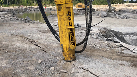
In rock, the relief cut is created as a slot or slotted bore pattern to prepare hydraulic splitting with rock and concrete splitting devices or rock splitting cylinders by Darda GmbH. Slots at the free surface or along planned fracture lines define the intended crack direction and reduce the risk of uncontrolled secondary breaks.
Natural stone extraction
In the extraction of natural stone blocks, relief cuts control block geometry. Slitting saws and slotted drill holes define the subsequent separation plane; hydraulic splitting then continues the crack calmly and reproducibly. The result is more uniform blocks and clean separation surfaces that simplify downstream processes. This supports natural stone quarrying applications.
Special applications
In special situations—such as the deconstruction of tanks or metallic vessels—relief cuts are used to reduce stresses and avoid uncontrolled cracking. Steel shears and tank cutters by Darda GmbH operate with predefined cutting zones, which increases safety and minimizes distortion.
Methods and cut types
Edge and corner relief
Relief cuts along free edges or at corners prevent stress from concentrating at geometric discontinuities. This reduces edge spalling when concrete demolition shears or shear-like tools engage afterward.
Guide cut for segmentation
Continuous cuts as predetermined breaking lines divide components into manageable segments. This facilitates lifting, reduces self-weight per segment, and stabilizes the process with rock and concrete splitting devices or concrete demolition shears.
Slot drilling and slotting
Overlapping core drill holes, optionally post-slotted, form a precise relief joint. This method is helpful when sawing is not possible or when low vibration is required.
Saw kerf and scoring cut
Shallow kerfs as scoring cuts protect visible surfaces and finishes. They define a clean termination and reduce visual damage during subsequent breaking or splitting.
Relief boreholes
Individual boreholes at crack tips, intersections, or at component ends have a stress-relieving effect. In combination with concrete demolition shears, existing cracks can thus be arrested.
Relief cut in combination with concrete demolition shears
Concrete demolition shears deliver their strengths when the fracture path is predetermined. With targeted relief cuts, the following effects can be achieved:
- Improved crack control: The fracture follows the specified line instead of wandering into reinforcement or adjacent components.
- Fewer edge spalls: Edges are protected by shallow scoring.
- Higher process reliability: The shear grips at defined attack points, often with better accessibility.
- Reduced load redistribution: Segmented components minimize unwanted deformations and reduce the risk of sudden secondary breaks.
Practical notes
- Guide cuts at corners and openings so that intersections are relieved (for example by small relief boreholes).
- Consider reinforcement: Choose the separation direction so that rebar can be cut free in a controlled manner.
- Provide attack points for the shear: Small recesses or kerfs improve positioning.
Hydraulic splitting: relief cut and rock and concrete splitting devices
In hydraulic splitting, crack formation is initiated by wedge forces. Relief cuts—as a slot or slotted bore pattern—reduce cross-sectional stiffness along the desired separation plane. Rock and concrete splitting devices as well as rock splitting cylinders by Darda GmbH then continue the separation with low vibration. This produces predictable fracture surfaces with minimal impact on the surroundings, which is crucial in tunnel construction and sensitive existing structures.
Planning: parameters that determine effectiveness
- Component thickness and geometry: Thickness, stiffness, edge distances, and existing joints influence the required depth and position of relief cuts.
- Material and structure: Concrete strength, aggregate, moisture, masonry bond, or rock joints determine crack guidance.
- Reinforcement and inserts: Location and diameter of bars influence cut routing and subsequent separation with concrete demolition shears.
- Environmental conditions: Vibration limits, dust and noise control, and water supply for cool and low-dust cuts.
- Load transfer and stability: Analyze load paths before cutting and provide temporary supports to prevent uncontrolled movements.
Execution tips
- Clearly mark cut lines and define the cutting sequence so that load redistributions remain manageable.
- Select cut depth and width to create a distinct weakening without undesirably reducing residual load-bearing capacity.
- Consider heat, sparks, and spray mist; implement suitable protective measures, especially indoors and in potentially hazardous areas.
- Plan for finishing: Smooth edges after separation if necessary to avoid subsequent damage.
Material dependencies: concrete, masonry, natural stone, metal
Concrete
In concrete, relief cuts are effective when they consider reinforcement layout and concrete structure. Crack control is particularly successful on slabs, walls, and upstands, where concrete demolition shears can then grip in a controlled manner.
Masonry
In masonry, bonds and bed joints are decisive. Relief cuts along mortar joints reduce flying debris and improve segmentability.
Natural stone
In natural stone, jointing controls cut routing. Slots along geological weaknesses facilitate subsequent splitting with rock splitting cylinders.
Metal
In steel plate and vessels, relief cuts serve to reduce stresses and minimize distortion. Steel shears and tank cutters benefit from defined start and end points to avoid cracks and uncontrolled tearing.
Quality assurance and documentation
- Define cut location, depth, and sequence in advance in a simple workflow plan.
- Visual inspection of edges and corners before subsequent use of concrete demolition shears or splitting devices.
- Photo documentation of separation surfaces and any spalling to improve processes.
Common mistakes and how to avoid them
- Unclear cut routing: leads to unpredictable cracking and additional work during breaking or splitting.
- Insufficient depth: stresses remain active, cracks migrate into undesirable areas.
- Ignored reinforcement: uncontrolled tie-ins to bars complicate separation with concrete demolition shears.
- Missing stabilization: components may yield uncontrollably after cutting.
- Unsuitable cooling or extraction: increases dust, heat, and edge damage.
Occupational safety and environmental aspects
The relief cut reduces vibrations and noise but does not replace fundamental protective measures. These include appropriate personal protective equipment, regulated dust and water management, and careful work near utilities, sensitive equipment, and existing building parts. In potentially hazardous areas—especially with tanks and metal vessels—additional precautions are required. The notes are general in nature and do not replace a project-specific assessment.
Practice-oriented application examples
- Wall opening in an existing structure: scoring cut along opening edges, followed by segment-wise breaking out with concrete demolition shears to protect edge areas.
- Slab segmentation: guide cuts in a grid pattern, then controlled separation and lifting of segments with minimal vibration.
- Rock splitting: surface slot as a predetermined crack line, followed by hydraulic splitting with rock and concrete splitting devices for calm fracture surfaces.
- Tank refurbishment: relief cuts for stress reduction, followed by defined separation cuts with steel shears or tank cutters to minimize distortion.