


Anchor plates are key components at the interface between steel construction and concrete or masonry construction. They transfer forces from columns, tie rods, anchors, or hanging systems into concrete, masonry, or rock and ensure uniform load distribution. In deconstruction they appear as fixed base or head plates that must be properly exposed, separated, or removed. For work involving anchor plates, tools and methods from concrete demolition and special demolition, strip-out and cutting, and—where rock anchoring is involved—from rock excavation and tunnel construction play an essential role. Products such as concrete pulverizers or hydraulic rock and concrete splitters from Darda GmbH are frequently used, without the task itself being tied to any specific brand.
Definition: What is meant by an anchor plate
An anchor plate is generally a flat steel plate that transfers tension, compression, shear, or moment forces from supported or connected components into a substrate. Typical applications include base plates of steel columns, head plates of tie anchors and grouted anchors, anchorages of machine foundations, brackets or façade holders, as well as head plates of rock bolts in rock and tunnel construction. The plate distributes loads over an area, limits local stresses, and enables adjustable, controlled installation using anchor rods, anchor bolts, or dowels. In existing structures, anchor plates often appear as visibly bolted or welded steel plates with round holes, slotted holes, stiffeners or shear tabs, and an undergrout made of grout mortar.
Configuration, shapes, and function of anchor plates
The configuration follows the basic principle of directing forces into the substrate. Depending on the task, anchor plates are rectangular, round, or polygonal. In addition to central holes, there are slotted holes for installation tolerances, countersinks for flush-head fasteners where applicable, and welded stiffeners to increase bending stiffness. For highly loaded base plates, shear dowels or headed studs are used to transfer shear forces positively into the concrete. Load transfer occurs via bearing pressure between the undergrout and plate, via tension in the anchor rods, and via friction and interlock. Concrete edge distances, anchor spacings, plate thickness, and stiffness decisively influence whether the demand is treated as membrane action, bending, or a combined effect. In terms of materials, unalloyed structural steels or stainless steels are often used. Corrosion protection is provided, depending on exposure, by hot-dip galvanizing, coating systems, or a combination. In rock and tunnel construction, anchor plates act as anchor heads: via nut and load washer they press loose rock against a shotcrete shell or the rock mass and thus secure the excavation support.
Design and planning: load transfer, geometry, and undergrout
The design is based on the governing load types: tension, compression, transverse forces, and moments. Calculation models consider the structural behavior of the plate (bending, membrane), of the fasteners (tensile capacity, concrete cone breakout, splitting), and of the substrate (compression cone, edge spalling). Essential aspects are adequate edge distances and spacings, the choice of plate thickness, limited hole clearance, and a capable, void-free undergrout. The undergrout made of non-shrink grout mortar ensures area-bearing load transfer and compensates unevenness of the concrete surface. For adjustability, the plate is aligned on leveling grooves or shims; the nuts are then tightened under control. For dynamic actions, preloading, anti-loosening measures, and regular inspections must be planned. In existing structures, a condition assessment should be carried out before interventions: visual inspection, determination of boundary conditions, rebar location, concrete cover measurement, and—where necessary—low-invasive testing.
Installation practice: preparation, installation, and inspection
Clean preparation determines quality. Before installation, the bearing surface and holes are freed from dirt and release agents. Anchor cages or anchor bolts are positioned with templates to ensure spacing and plumb alignment. After aligning the anchor plate, the undergrout follows; ensure adequate feed openings, venting, and a continuous material flow. After the required strength is reached, nuts are tightened to the specified torque and—if provided—marked. Documentation includes measurement records for sealing layers, flatness, edge distances, and torques. In corrosion-prone environments, edge rounding, coating thicknesses, and void-free undergrout are particularly important.
Anchor plates in concrete demolition and special demolition
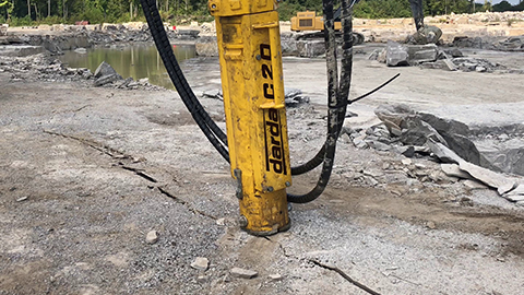
In deconstruction, anchor plates often only become visible after exposure. For foundations with heavily reinforced concrete, controlled removal of the concrete is recommended to reach the plate, anchor rods, and any shear dowels. Darda GmbH concrete pulverizers enable targeted crushing of the concrete, reduce vibrations, and minimize damage to adjacent components. When massive concrete sections or anchor groups impede access, stone and concrete splitters can induce cracks that open the concrete along desired separation planes. This facilitates access to nuts and the undergrout. Protruding anchor rods are cut off—depending on boundary conditions—with steel shears or multi cutters; for large-format plates, workflows with steel shears or tank cutters must be planned. mobile hydraulic power units supply the tools with the required energy and allow low-vibration operation. The choice of method is based on member thickness, reinforcement content, spatial constraints, and requirements for noise reduction measures and dust suppression.
Strip-out and cutting: creating access, planning separation points
During strip-out, fit-out trades, claddings, or machinery are dismantled to make anchor plates accessible. Clear planning of separation points prevents uncontrolled failure when releasing the last fasteners. Concrete pulverizers are suitable for exposing the undergrout without damaging the plate itself. Where space is limited and in sensitive areas, stone and concrete splitters enable silent separations. For cutting metallic components—depending on material thickness and accessibility—steel shears, combination shears, or multi cutters are used. When releasing pre-tensioned components, controlled unloading steps must be planned; work on load-bearing connections may only proceed in a coordinated sequence.
Rock excavation and tunnel construction: anchor plates as anchor heads
In tunnel works and rock slopes, anchor plates appear as visible anchor heads. Via nuts and load washers they press the lining against the rock mass and stabilize the excavation or opening. For adjustments or deconstruction, anchors must be secured, de-tensioned, and documented before plates are released. For exposure in a shotcrete environment, gentle methods with low vibration input are suitable. After releasing, anchor rods are shortened or removed. In special operations, such as subsequent strengthening or retrofit in portal areas, re-evaluation of load paths is essential; temporary shoring and a step-by-step approach reduce risks.
Repair and strengthening of anchor plates
In existing structures, corrosion, inadequate undergrout, or faulty load distribution can cause damage: loose nuts, cracks in the undergrout, concrete spalling, or plate deformation. Repair measures range from renewing the undergrout, retightening and securing nuts, to replacing the plate. For increased loads, additional anchors are added, stiffeners are welded on, or shear dowels are retrofitted. Corrosion protection systems are renewed after suitable substrate preparation. Work on the load-bearing system requires project-specific planning; temporary shoring and torque checks are standard.
Typical failure modes and how to avoid them
Common errors include insufficient anchor edge distances, excessive hole clearance without shims, missing or voided undergrouts, poorly deburred plate edges, and uneven nut tightening. This leads to eccentricities, local stress peaks, concrete cone breakout, or creep behavior in the connection. The remedy is careful installation planning, adherence to the tightening sequence, control of undergrout quality, and protection of exposed edges. In deconstruction work, unintended severance of load-bearing anchors must be avoided; load-bearing functions must be identified in advance and temporarily secured.
Safety, notes, and responsibilities
Work on anchor plates usually involves load-bearing connections. Planning, execution, and control should be carried out by competent professionals. In deconstruction, shoring, load rerouting, and exclusion zones must be provided. Welding, cutting, and hydraulic work require appropriate personal protective equipment and a hazard analysis. Standards and recognized rules of practice must be observed; legal requirements may vary by project and region. The information in this article is of a general nature and does not replace project-specific planning.
Practical guide: methods and tools by task
Exposing undergrout and anchors
For gentle removal of concrete around the plate, concrete pulverizers have proven effective. For massive sections or dense reinforcement, stone and concrete splitters generate crack lines that can be opened in a controlled manner. This provides access to nuts, washers, and shear dowels.
Separating metallic components
Protruding anchor rods and stiffeners can be cut off with steel shears or multi cutters. Large-format plates or tank pedestals can—after structural unloading—be segmented with tank cutters or combination shears. Hydraulic power packs provide the energy supply and allow mobile work in confined areas.
Special use cases
In natural stone extraction or for temporary installations on rock, anchor plates are part of temporary anchorages. Deconstruction requires orderly de-tensioning of the anchors followed by targeted release of the heads. In special operations, such as work on contaminated facilities, protective and cutting methods with low spark generation determine the choice of tools.
Project workflow planning: from survey to documentation
A structured process starts with the survey: location of anchors, plate dimensions, condition of the undergrout, and corrosion state. This is followed by selecting methods, defining the sequence of exposing, separating, and disposal, and creating exclusion and protection concepts. During execution, measurement points, torques, material batch numbers, and test results are documented. Finally, surface protection measures and—where anchor plates remain in place—verification of tightening values ensure durability.