


Transverse load describes laterally acting forces that stress components, materials, and tools perpendicular to their longitudinal axis. In concrete demolition, specialized deconstruction, rock excavation, tunnel construction, and natural stone extraction, how transverse loads are managed determines safety, efficiency, and structural behavior. Tools such as concrete demolition shears, rock and concrete splitters, combination shears, steel shears, Multi Cutters as well as tank cutters and the associated hydraulic power packs from Darda GmbH frequently encounter situations in practice where shear force, shear stresses, bending, and torsion act simultaneously. A systematic understanding of this lateral loading reduces uncontrolled fractures, minimizes consequential damage, and supports planned deconstruction.
Definition: What is meant by transverse load
Transverse load refers to a force or load component acting perpendicular to the principal axis of a component or workpiece. It leads to shear force and associated shear stresses, often combined with bending moments when introduced eccentrically. In concrete, steel, and natural stone, transverse load manifests, among other things, as inclined cracks (shear cracks), spalling at edges, crushing in contact zones, and potentially unstable tipping movements. On attachments—such as concrete demolition shears or rock and concrete splitters—transverse load can occur at gripper arms, joint pins, cylinders, and knife or jaw edges, particularly with an oblique approach, asymmetric support, or uneven clamping.
Physical principles of transverse load
Transverse loads generate shear stresses in cross-sections and, depending on the lever arm, lead to bending and tipping. In practice, purely transverse load cases are rare; combined loading from shear, bending, and torsion is common. The magnitude of transverse loading depends essentially on support conditions, contact surfaces, eccentricities, member thickness, material strength, and existing weakness zones (reinforcement layers, bedding planes, joints).
Shear force and shear stresses
Shear force produces shear demands in components. In reinforced concrete, diagonal shear cracks occur in regions of high shear near supports or concentrated loads, while in natural stone, slip-like fracture patterns can occur along bedding or joint planes. Local shearing also arises in contact zones between tool and workpiece.
Bending due to eccentric transverse loads
If the transverse load does not act through the shear center, an additional bending moment is created. Thin slabs, walls, and decks are particularly sensitive: even small eccentricities or insufficient intermediate supports can cause unwanted deflection, cracking, and edge breakouts.
Torsion and combined loading
Oblique attack, uneven material removal, or asymmetric gripping widths generate torsion. Combined loading increases the risk of failure as stresses superimpose. Multi Cutters, combination shears, and steel shears can experience lateral forces and moments in frames, pins, and cylinders under such conditions.
Transverse load in concrete, steel, and rock
Material-specific properties determine how transverse loads act and which failure mechanisms dominate. Therefore, the choice of approach—such as using concrete demolition shears versus a rock and concrete splitter—must always be evaluated in the context of material, member geometry, and support conditions.
Concrete and concrete demolition shears
Concrete is strong in compression but sensitive to tension and shear. Concrete demolition shears concentrate forces at the jaw edges and create local compressive and shear stresses. A favorable jaw position—close to support zones or with short spans—reduces bending and thus the transverse load on the component. Diagonal shear cracks typically appear between the load application and the support. Edge distances, grip angles, and the sequence of bite points influence the crack pattern and the magnitude of lateral loads.
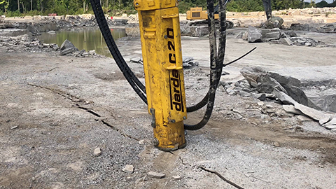
Rock, natural stone, and rock and concrete splitters
Splitting deliberately induces tension perpendicular to the borehole axis. Transverse loads occur when support is uneven, borehole spacings vary, or the split wedge is applied eccentrically. In layered rocks, transverse loads tend to cause flaking along bedding rather than clean split faces. Precise alignment of stone splitting cylinders and uniform build-out of supports limit lateral forces.
Steel sections, tanks, and sheet-metal structures
With steel shears and tank cutters, transverse loads can trigger local buckling, web shear in I-sections, or edge bulging in sheets. Thin-walled components react sensitively to eccentric application and large-area crushing. Interlayers and soft underlays distribute contact pressures and reduce peaks in lateral loads.
Influence of transverse load on tools and hydraulic systems
Transverse loads act not only in the workpiece but also in tool structures. Joint pins, bushing bearings, frames, and cylinders of concrete demolition shears, combination shears, or Multi Cutters experience additional edge stresses when lateral forces occur. A maximally axial load path through the jaw and knife lines increases mechanical stability.
Hydraulic power packs and lines
Hydraulic power packs—also referred to as hydraulic power units—provide the pressure and flow that are converted into mechanical work at the tool. Lateral loads are not stored in the oil but influence the load path through reaction forces. Vibrations caused by laterally acting impacts can dynamically stress couplings, hoses, and threaded connections. Stress-free hose routing, kink protection, and short, clear load paths in the attachment reduce consequential loads.
Application examples in the fields of use
Depending on the field of use, transverse loads present differently. Geometry, support, and work sequence are decisive.
Concrete demolition and specialized deconstruction
Slab fields often experience increased transverse load during deconstruction due to changed spans. Concrete demolition shears should be guided so that the remaining field width stays small. Temporary shoring shortens lever arms and reduces peak shear at supports.
Strip-out and cutting
Cutting wall openings or detaching attachments creates new free edges. Tank cutters and Multi Cutters should be applied to prevent thin-walled areas from being deformed by eccentric transverse loads. Catch structures and defined cutting sequences limit bending and lateral load.
Rock excavation and tunnel construction
Rock and concrete splitters transmit forces via borehole groups. Asymmetric hole patterns or varying rock qualities produce lateral reaction forces. Symmetric hole arrangements and coordinated firing or pressure sequences reduce transverse loading.
Natural stone extraction
Orientation relative to bedding is crucial. Transverse loads across the layering increase the need for interlayers and areal support. When loosening and tipping blocks, lever arms should be kept short to avoid edge breakouts.
Special operations
Unusual geometries, mixed constructions, and restricted accessibility increase uncertainty about load paths. Trial bites with low force, stepwise dismantling, and close monitoring help detect peaks in transverse load early.
Design and estimation of transverse loads on site
An exact analytical determination is not always possible in deconstruction. Practical estimates and observations improve safety.
- Span and supports: the greater the free length, the higher the bending moments from transverse loads.
- Eccentricity: an oblique approach increases tipping moments and torsion.
- Cross-section and thickness: thin members are sensitive to transverse load.
- Contact area: small support areas create high contact pressures and local shearing.
- Material disposition: reinforcement layers, bedding, joints, and fractures influence shear capacity.
- Create or widen supports (underlays, props, wedges).
- Define cutting and biting sequence to shorten spans.
- Select the grip angle so forces are introduced as axially as possible.
- Use interlayers to reduce edge contact pressures.
- Continuously observe crack-forming zones and adapt the working method.
Typical failure patterns and damage progressions
Understanding recurring patterns helps identify and prevent transverse load issues.
- Diagonal shear cracks in reinforced concrete near supports and concentrated load applications.
- Edge breakouts and spalling under eccentric gripping positions of the concrete demolition shear.
- Sliding along joints or bedding planes in natural stone under lateral loading.
- Local buckling in sheets during tank cutting due to uneven support.
- Increased wear on pins, bushings, and jaw edges due to recurring lateral forces.
- Transverse loads on piston rods leading to seal wear and uneven running marks.
Practical approaches to limit transverse load
The goal is a clear, short load path, small lever arms, and uniform pressure distribution.
- Shoring and intermediate supports: introduce load over larger areas, use hardwood or rubber inserts.
- Gripping strategy: several small bites instead of one large bite to avoid peaks in transverse load.
- Observe edge distances: do not engage immediately at free edges.
- Plan cutting sequence: reduce edge fields first, then release main fields.
- Ensure axial alignment: align tools with member axes to minimize lateral forces.
- Low-vibration working: reduce impact loads to lower dynamic transverse loading.
Specific guidance for concrete demolition shears
Guide jaws as parallel as possible to the member surface and place the bite near supports. For slab fields, remove cantilever areas first to shorten the free span. In beams and girders, stagger bites so shear cones do not overlap unfavorably. In reinforced concrete, inclined tension and shear cracks are to be expected; adjust grip points accordingly.
Specific guidance for rock and concrete splitters and stone splitting cylinders
Align borehole axes and choose uniform spacings. Avoid eccentricity of split wedges to reduce lateral reaction forces. In layered rock, choose the splitting direction relative to bedding so transverse loads do not cause flaking. Interlayers made of dimensionally stable materials distribute contact forces on uneven supports.
Safety and organizational aspects
Safe work under transverse load requires a combination of planning, observation, and adaptation. Hazard assessments, recognized engineering standards, and adherence to Darda GmbH operating manuals form the framework. Information is to be understood as general and does not replace a case-by-case assessment.
Personnel and qualification
Operators should be trained to recognize crack patterns, tipping movements, and unexpected deformations. A shared understanding of work sequence, shoring, and early signs of transverse load issues facilitates decision-making on site.
Documentation and monitoring
Continuously document observations on cracks, wear patterns, and readjustments. Even small changes in crack geometry or tool sound can indicate increasing transverse loads.
Maintenance and inspection in the context of transverse load
Transverse loads accelerate wear at contact and bearing points. Regular checks ensure the functionality of tools and power packs.
- Check joint pins and bushing bearings for play and uneven wear.
- Inspect jaw, knife, and gripping edges for notches and asymmetric wear.
- Check cylinders and piston rods for lateral running marks and seal condition.
- Inspect hoses, couplings, and threaded connections for signs of dynamic loading.
- Retighten bolted joints, especially at attachment points with bending and transverse load components.
Terminology and classification within deconstruction
Transverse load interacts with axial normal forces, bending, and torsion. In practice, there is an interplay: shear force generates shear, eccentricity produces bending, and asymmetric removal yields torsion. Deliberately reducing eccentricities, enlarging contact areas, and using controlled work sequences help keep these effects in check—regardless of whether concrete demolition shears, rock and concrete splitters, combination shears, steel shears, tank cutters, or Multi Cutters are used.